So now we come to the first part of the booster, which is the application of the motor mount and the two corrugated skirts. As I mentioned in the previous post, Sandman sent in that illustration of the A-001 flight qualification vehicle and it provided me with an opportunity to dress up the model just a little. Please understand, I am not a scale competition builder, and even I recognize some obvious flaws in my handiwork. However, even the modest trims I've added will improve the kit's appearance, especially once the primer and the paint have covered all of the most critical visual flaws.
Attaching the motor mount was relatively simple. The fit was loose, so I had to do the glue-up in two steps. For the first step, I placed the main body tube upright on my desk and slid the mount down from the top, until the hook was touching the desk. This makes the hook tip even with the bottom edge of the tube. Next, I mixed up a 50-50 dilution of yellow glue and ran a few generous drops around the outer edge of the upper centering ring.
I allowed this to dry overnight before flipping the tube over and doing the same thing with the lower ring.
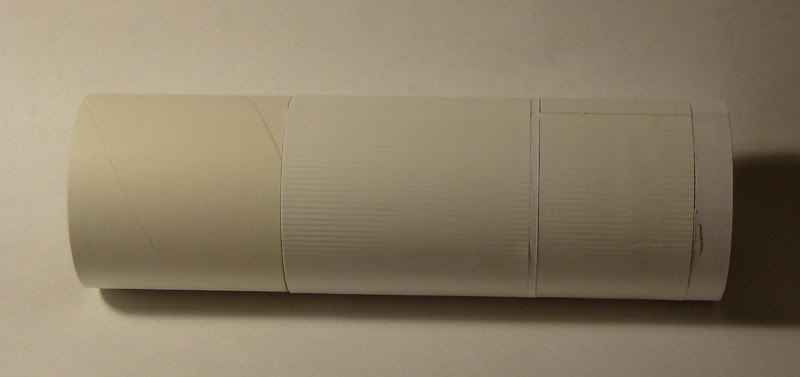
Once the rings were dry, I started on the skirts. The kit has no real detail on the booster, except for the skirts, and these are incorrectly sized relative to the actual vehicle. The lower skirt is too tall, and the upper skirt is too short, placing the separation joint farther up the side of the body than it should be. I elected to keep the skirts as they came instead of modifying them. But I did attempt to trim out the skirts with some label paper separation panels, based on Sandman's drawing.
Starting with the lower strip, we need a 10mm high panel that goes completely around the body, even with the bottom edge. Here's that panel applied:
It takes three thicknesses of label paper to equal the thickness of the skirt. Next we add that short skirt (

) to the model, using full-strength Titebond II. The glue needs to be spread evenly and thinly to prevent blisters under the skirt.
No, I didn't get all of the blisters out from under it; they are quite visible in several places. No room for those pictures, however...
The separation strip is made from three thicknesses of label paper, 2mm wide, and is applied directly above the lower skirt. I followed this with the upper skirt.
Just above the upper skirt is yet another separation band, where the booster and the boilerplate service module came together. Shown here is one of the upper straps being applied:
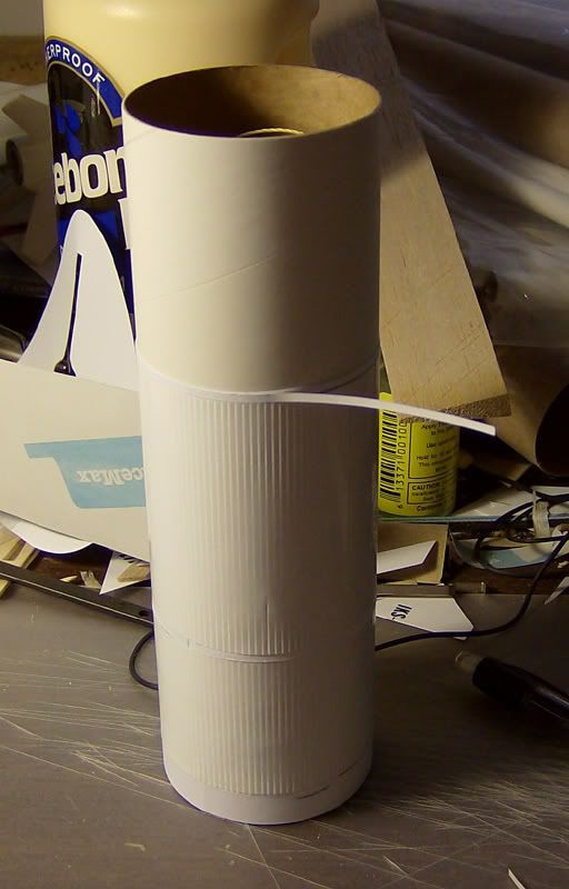
Once these straps are in place, I sealed the upper strap with CA, then sanded the excess off.
Now we come to a more prominent detail that cannot be left off, or it would be quite conspicuous by its absence. These are the two flat conduits that run vertically along the sides of the body, 180 degrees apart. I simulated this with more label paper:
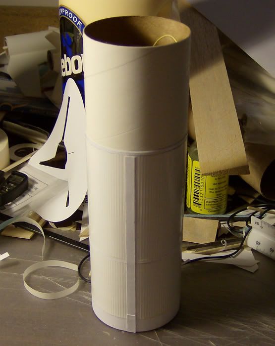
This side conduit does two things for the model: It is visible, and it covers the splice joint in the skirts. These areas, when painted, are supposed to be natural aluminum in color, while the command and service modules are supposed to be white. The only trim color is black, and the decals in the kit should be close enough for the service module.