
|
SEMROC Little Joe II Building Thread
This thread is meant to parallel the similar thread for the Saturn 1B, since both models use the same Apollo Capsule kit. It is not meant as a competitor to that thread, but as a complement since both models are of the same vintage and historical importance. While a great deal of time is spent working on the Apollo portion of the model, there are other aspects of the LJ-II that have similar requirements, such as the application of wraps and the built-up fins. What I want to try to do is document the construction using some techniques I found helpful, and any pitfalls I may run across, during the process.
|
Construction Begins! [Bandwidth Alert!]
This first section begins where most models begin -- with the motor mount. The use of laser-cut components makes this process so much easier, and Carl is to be congratulated for the accuracy of these parts. I found them to slip together with just enough friction to keep them from excessively moving around while gluing, but not so much that I needed to sand the rings to make them fit over the motor tube.
The first image show the mount in partial profile, after initial fitting and glue-up: 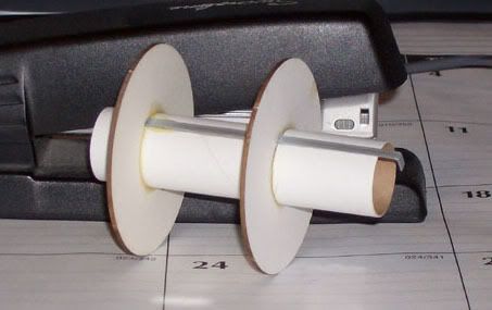 Beginning with the assembly of these parts, I made a change from the instructions. I wanted a tighter fit of the rings over the engine hook, but without crushing the tube by trapping the hook under the ring. To get this fit, I sanded some shallow flat notches in both rings. The next image shows the tool I use to sand these notches: 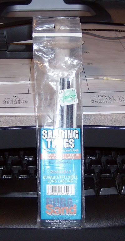 Using one of these twigs, the same width as the hook, I carefully sand a shallow flat notch in each of the rings, with the one in the normal lower ring directly opposite the pre-cut engine hook opening. This allows the rings to fit more snugly over the hook, holding it in position better. Next, the former lower ring will become the top ring: 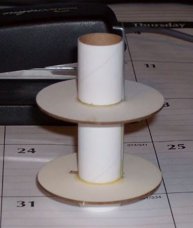 What I am now able to do is tie the Kevlar thread around the motor tube, and run it through the larger slot: 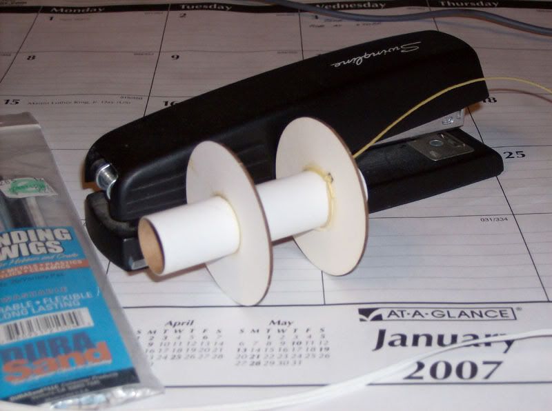 I use these CA applicators to put the glue to the joints: 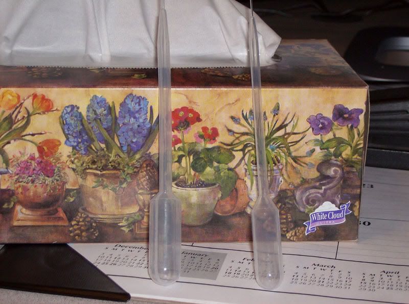 I am using Titebond II for this project, which is my glue of choice for building most models. The glue is applied thin -- about 50-50 with water -- and this allows the glue to wick into the joints and get deep into the "roots". When the first layer is dried, apply a second layer right over it and this will secure the parts without the typical waste of glue. It really doesn't take that much glue to work with these paper components. Once the glue dries, these parts are rock-solid. Now, I attached a snap swivel to the free end of the elastic chord:  Here is the snap swivel attached:  And now, the motor mount subassembly is complete, ready for insertion into the body tube:  This ends the first part of the project. Next message will deal with the fins. |
Wonderful pictures!
Keep it going. |
Great build pics! But, I wanted to see what the Little Joe II looks still "in-the-bag" before
the build begins... (not too late for that, isn't it?) |
Quote:
Uhhh, 'fraid so... Sorry. I'll have to get another one for bag shots...:D |
Quote:
I'm sure someone has an unbuilt kit. |
I guess I'm the only one who builds a house from the top down?????
I wish I had seen this before I started building!!! Seriously, You are truly skilled and experienced rocketeer. Your pictures and descriptions are worthy of a "How to build rockets" handbook. But I get sooooo excited I sometimes seal the cone, mount the fins and paint and decal, without even a mmt or recovery given a thought. On one occasion, I had to glue a centering ring down a rockets throat with shock cord on a year old build while prepping for the next day's launch. I must follow the directions next time! Bob |
Quote:
You've only had to do this once??? And you call me experienced! :o |
Fin Assembly
The fins are very lightweight, both in mass and in construction. As shown in the original instructions, you build a frame around the outside edges of one side of the folded cardstock skin, then fold the other side over and glue it to the frame. Carl's tight laser cuts a clean line for these pieces, and the wedge-shaped pieces are accurate, but the pieces themselves don't quite fill up the gaps at the corners. The long straight piece is a tad short; meaning you wind up with two pieces of balsa just barely touching on the inside corners, and a big gap to fill on the outside corner. A better fit could be achieved if the long piece was about a 16th inch longer, and bevels were sanded into the ends to meet the short straight piece and the root-edge long wedge.
A second issue is a product of the overall frame design. The large central piece of balsa that ties the frame together between the wedges is glued to the skin on one side only. This leaves one whole skin side unsupported, and thus allows for acceleration-induced collapsing of the skin during launch. On a high-power "C" launch, this could lead to a vectoring of the slipstream by the fin shape, causing a roll in one direction. While this may not be a big issue, and the resulting spin may add some stability to the model, I think in a future build I might have to use a thicker piece, like 3/32" or even 1/8", and sand it to a matching wedge shape before fitting it into the frame. This would allow both skins to have contact with this member and the fin would retain its shape better. These issues are simply a result of following the original version closely, and not a criticism of Carl or his work. These issues existed in the original kit 37 years ago, and they remain today. First image shows the four fins together, one completed: 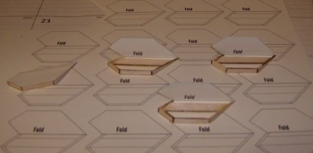 Here's the assembled fin, all nicely closed up: 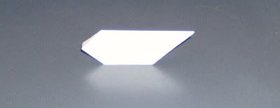 Here's one of the still-open fins, showing the frame gaps: 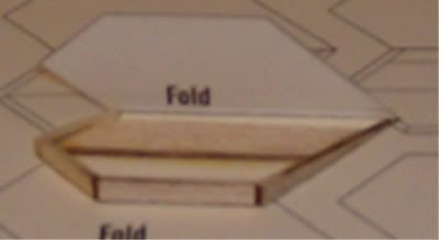 In this last image (sorry for the blur -- inside shooting, flash, low-light, close proximity...) you can see how the large member fits against one side of the fin but doesn't touch the other. The skin on this side is supported solely around the edges. This piece needs to be thicker, and sanded to match the wedges. Doing this will allow the skin to be supported along the center. I used full-strength Titebond II applied with a small artist's brush. Lay down a thin layer onto the skin first, then apply a layer to the wood piece before setting it in place. The full-strength glue has the "tack" you need to hold things in position. You will note the fins are sitting on a full sheet of skin images. After building the first fin with thinned glue, I found the moisture deformed the skin too much. I wound up having to cut new pieces from scratch for one fin, and needed at least one fresh skin to finish the work. Next: Attaching things to the body... |
I thought the same thing about the center balsa piece. At first I wondered why the original was done that way. I then thought that some builders wouldn't be able to get a good fit and would end up with a bulge across the length of the fin. I doubt I'll ever fly mine on a C motor, so I'm happy with it like it is so far.
I've built the escape tower legs and I'm now on the center support structure. I got tired of doing the tiny detail work so I ut it away for a while and I've built a couple of regular rockets like the Nike-X to rest my eyes. :) I'll get back to the LJ II in a few days. |
Quote:
Since I haven't closed up the three clams yet, I'm going to cut some additional center pieces from some soft balsa and fit it in place, and then sand them to match the wedges. It also means I need to cut out one additional set of pieces and build yet another fin. I agree, a "C" motor is just way overkill power for this model. I might consider an occasional "B" flight, but I'll probably limit it to an "A" most of the time. |
Taking an alternate route...
Sometimes the original way to do something just ain't the best way to do something, no matter how nostalgic it might seem. Case in point -- the LJII fins. As I tried over and over to get those skins to work out, I kept getting bad results and no real satisfaction. I kept thinking, "How much those fins need to have a full balsa core". But then, I also kept thinking, "How much of a bear those fins would be to sand into that wedge shape..."
My RC builder's sensibility kicked in last night, and I realized I actually had something in my wood piles that was perfect for this task. It's known as "Aileron Stock", and can be purchased in just about any LHS. See the first image: 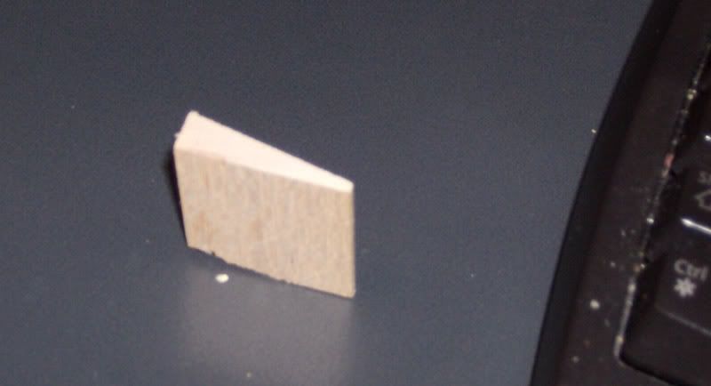 This piece of pre-shaped balsa measures 1 1/4" wide and 3/8" tall, and comes in 36" lengths. I had two sticks in the pile. Selecting one, I cut off a 3" long piece and marked both sides with a piece of the cardstock containing all those lovely printed fin images. Starting with the long wide edge of the fin, I cut through from one side about half-way, flipped the piece over, and cut through the remaining excess. This left me with a gentle, sandable hump along the wide edge. Using a "T-Bar" sanding tool, I flattened this edge. Next, I cut the remaining edges, ending up with this: 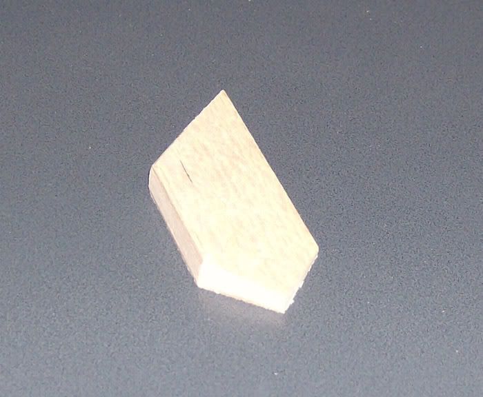 Now I have a solid fin with no ridges, dips, or other gross visual imperfections. All I need to do now is apply the label stock around the sides and edges. If there is a drawback to this method, the solid fin is just a fraction thicker than the built-up fin. Unless you are looking at the original kit fin, this is completely un-noticeable. Weight-wise, it doesn't feel any heavier or any lighter. Actually, it feels about the same weight. Here is a comparison between the raw stock and the finished fin: 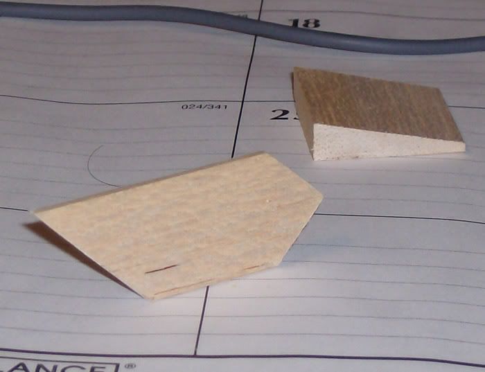 And another view: 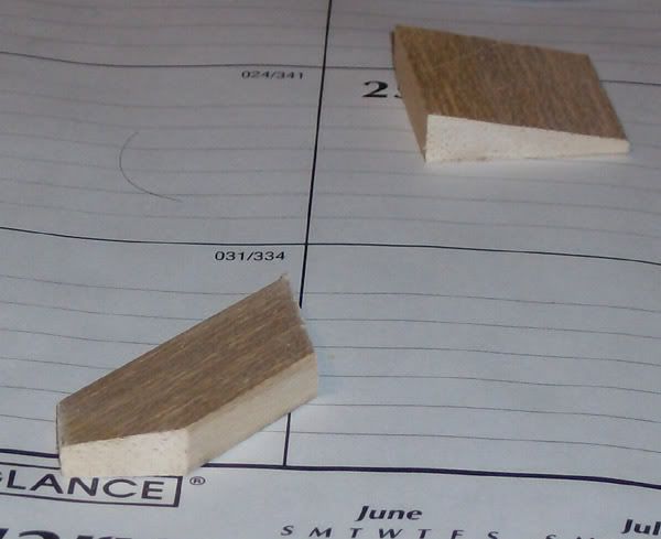 I'll continue with the assembly sequence as soon as I finish the remaining fins. I think this is the better way to handle this issue, and provides the more consistent final product. Till next time... |
Craig,
That is NOT a new idea. Using trailing edge stock is exactly what Centuri did for their 1/45th Little Joe II kit. :D Gees, you would have thought Carl would have come up with that. Actually Carl was just sticking to the original Estes version. I copied the trailing edge stock idea with my 1/35th LJII and my LTV Scout kits. Now if you cover the trailing edge stock with the cardstock from the SEMROC kit...badda bing, badda boom! No balsa to seal! ;) And those puppys are strong! |
Quote:
It is when the idea hits you at 2 AM... :D Quote:
Actually, that's what I should have said -- Trailing Edge stock; Aileron stock is similar, but has a half-round cut into the thick edge. Quote:
I was thinking about the self-stick labels sealed with CA, like we've started doing with other models. Cardstock would give it a tougher surface, though. It would be that much thicker, too, but it would still look right. |
2 Attachment(s)
The trick is to cut the trailing edge to fit the cardstock (mainly the patterns in the SEMROC kit) Don't make the cardstock fit the trailing edge.
Does that make any sense at all??? :confused: These could be a better pictures but I think you could get the idea. This is of my 4" LJ II. My original is starting to show signs of wear after 10 flights. :o I have a set of the 1/70th vacuform parts from Paul Graf so I can do a really detailed 1/70th version...someday when I have time... :rolleyes: |
1 Attachment(s)
While looking through my "stuff" on my LJ II kit I came across some body wraps of the upper section of the LJ II. The Service Module area.
If anybody wants them I have redrawn the different rounds A-001 through A-004. I can post them if you looking to get a bit closer to scale and don't feel like a lot of masking and paint. I also can scale down the detail lower pattern for placement of all the bumps, conduits and stuff on the bottom. The one here is for round A-004 |
Will this wrap fit the 1/70 scale (BT-70) if I print it at 100%?
|
Quote:
It should. I make these drawings up in CAD and my program prints perfectly. But... I print it to pdf to make the file since I can't attach CAD files here. Hey...try it...it's only paper! Does anybody know what round the SEMROC kit is? It can't be A-002, A-003 or A-004 'cause that uses the fin fairings. It has to be A-001. In that case the wrap is too big vertically. I'll redraw it correctly tomorrow...gotta go out tonight. |
Quote:
I think someone has mentioned it before, maybe it was Carl, maybe even on the instruction cover, that this model represents A-001. This was the only LJ-II that had fixed fins; all of the others had the adjustable / power-boosted type, and their requisite power conduits along the body. A-001 didn't have these conduits. |
2 Attachment(s)
Quote:
Yes, it has to be A-001. Fixed fins and no fin fairings. Maybe this will help. I'll work on the upper wrap. edit* I got the wrap done. NOTE!!! Round A-001 does NOT have RCS thrusters! That was probably Estes error if you are trying for scale points! |
Thanks for the datasheet, Sandman. I think I'm going to dress it up a bit now; I can see a couple of easy enhancements from those drawings.
|
Booster construction
So now we come to the first part of the booster, which is the application of the motor mount and the two corrugated skirts. As I mentioned in the previous post, Sandman sent in that illustration of the A-001 flight qualification vehicle and it provided me with an opportunity to dress up the model just a little. Please understand, I am not a scale competition builder, and even I recognize some obvious flaws in my handiwork. However, even the modest trims I've added will improve the kit's appearance, especially once the primer and the paint have covered all of the most critical visual flaws.
Attaching the motor mount was relatively simple. The fit was loose, so I had to do the glue-up in two steps. For the first step, I placed the main body tube upright on my desk and slid the mount down from the top, until the hook was touching the desk. This makes the hook tip even with the bottom edge of the tube. Next, I mixed up a 50-50 dilution of yellow glue and ran a few generous drops around the outer edge of the upper centering ring.  I allowed this to dry overnight before flipping the tube over and doing the same thing with the lower ring.  Once the rings were dry, I started on the skirts. The kit has no real detail on the booster, except for the skirts, and these are incorrectly sized relative to the actual vehicle. The lower skirt is too tall, and the upper skirt is too short, placing the separation joint farther up the side of the body than it should be. I elected to keep the skirts as they came instead of modifying them. But I did attempt to trim out the skirts with some label paper separation panels, based on Sandman's drawing. Starting with the lower strip, we need a 10mm high panel that goes completely around the body, even with the bottom edge. Here's that panel applied: 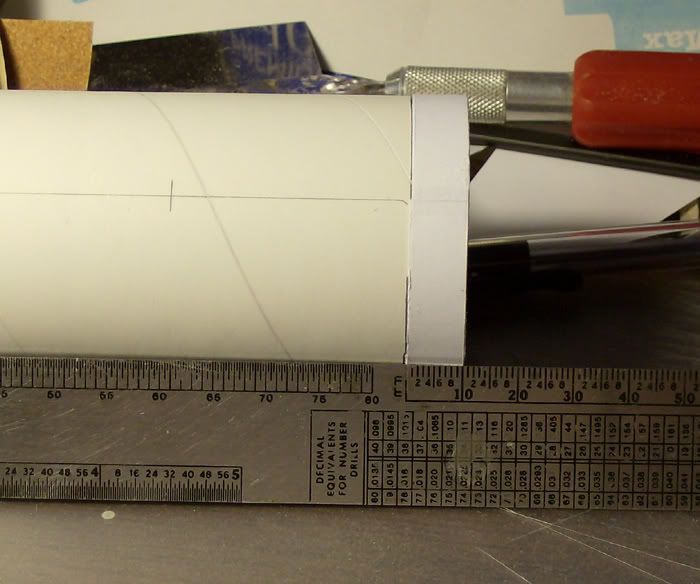 It takes three thicknesses of label paper to equal the thickness of the skirt. Next we add that short skirt (:o ) to the model, using full-strength Titebond II. The glue needs to be spread evenly and thinly to prevent blisters under the skirt. 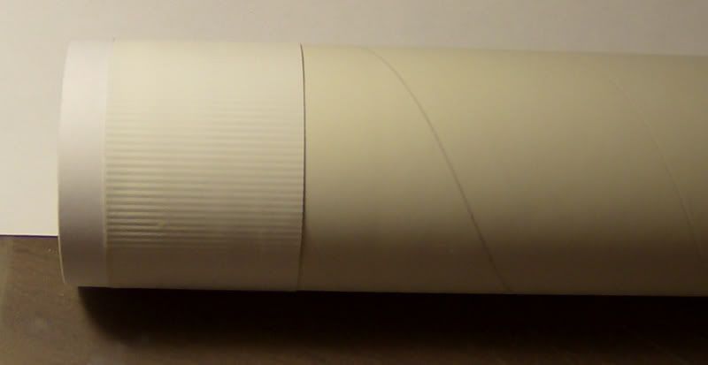 No, I didn't get all of the blisters out from under it; they are quite visible in several places. No room for those pictures, however... The separation strip is made from three thicknesses of label paper, 2mm wide, and is applied directly above the lower skirt. I followed this with the upper skirt. 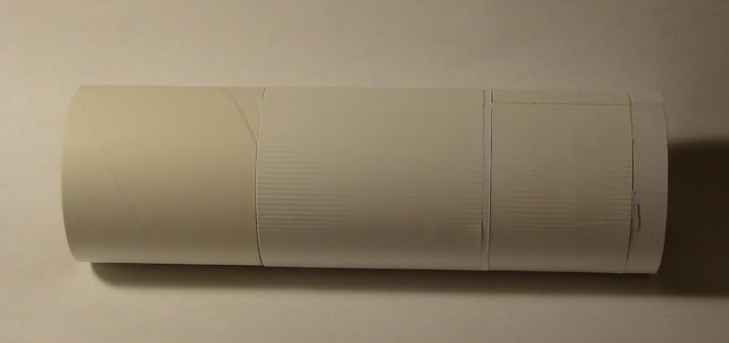 Just above the upper skirt is yet another separation band, where the booster and the boilerplate service module came together. Shown here is one of the upper straps being applied: 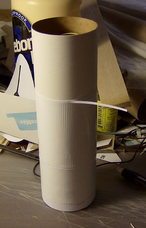 Once these straps are in place, I sealed the upper strap with CA, then sanded the excess off. Now we come to a more prominent detail that cannot be left off, or it would be quite conspicuous by its absence. These are the two flat conduits that run vertically along the sides of the body, 180 degrees apart. I simulated this with more label paper: 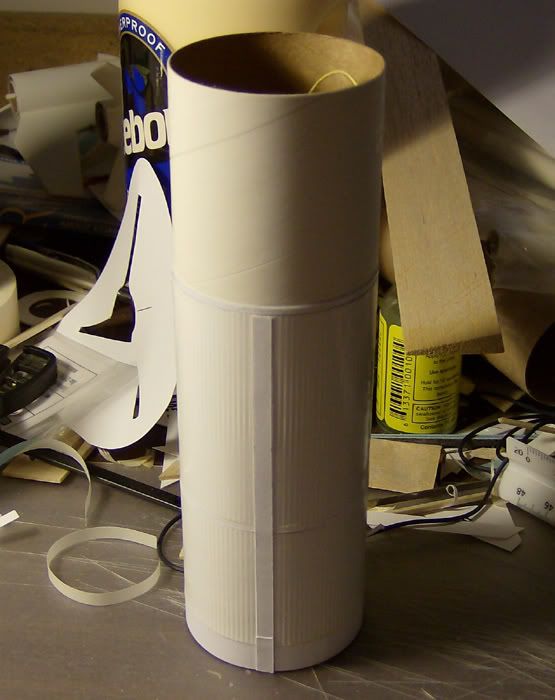 This side conduit does two things for the model: It is visible, and it covers the splice joint in the skirts. These areas, when painted, are supposed to be natural aluminum in color, while the command and service modules are supposed to be white. The only trim color is black, and the decals in the kit should be close enough for the service module. |
1 Attachment(s)
Yer gettin' ahead of me!
Here's the lower wrap pattern. |
I had the same bubble trouble on the wraps with mine. I don't know how much of the bubbles are air and how much are glue. I tried to remove excess and leave a thin film, but I think it collected as I rolled and smoothed the wrap. The bubbles were all toward the end of the wrap, not at the beginning.
|
Quote:
Same problem here. There are places where I've rubbed the ribs out completely trying to work the glue (or air) out. I think it's mostly glue, because it makes the wrap feel spongy (like moisture). |
Quote:
I gave up trying to get them out before rubbing the ribs down very far. The moisture softened the wrap making the effect even worse. I used contact cement for the Centuri Saturn 1B and V plastic wraps years ago... a different animal, no doubt. But I think I used it on the Estes Space Shuttle wrap on the external tank a few years later also. I believe I'll go with that on the Semroc Saturn 1B because the external tank doesn't show any of the problems I had with the LJII and it's also a paper wrap. I wish I could remember for sure what I used on it. |
Quote:
I was going to mention contact cement, which is what I'm going to use when I do my Estes 1/70 Saturn 1-B kit. Contact cement doesn't give the bubbling/warping problems the regular glue does, but you do have to be extra certain you have your aligment(s) correct or you don't get a second chance. |
Yes transparent glue
I discovered an permenant stickflat "gluestick" glue a few years ago. It works great on paper and can be watered down to a desired consistancy. Also works on cloth, leather, glass, metal, and wood. I found it a Micheal's if my memory serves me. It comes in a 1lb 3 oz. jar and it is called:
YES manufacured by Gane Brothers & Lane Inc. Elk Grove Village, IL Hope this helps, JP James Pierson NAR# 77907 |
I've got an unfinished Estes Saturn V 25th anniversary with paper wraps. I looked at it while ago and the wraps look really good. It looks like I used Elmer's white glue on it as there is no yellowing at the edge of the wraps that would show with yellow glue, nor brown from contact cement. That means one of three things were different from the LJ-II application.
1. White glue might not have caused bubbling (didn't soak in and soften paper like yellow did?) 2. Estes paper wraps may be different allowing easier application 3. I have lost a lot of skills over the years since I started the Saturn... :eek: Maybe a combination... |
Quote:
Yes, I did; and I see a correction that needs to be made. The flat conduit opposite the skirt wrap seam doesn't go above the separation between the two skirts. I need to trim this conduit per this new drawing. That is a highly noticeable error. Thanks again, Sandman! |
Quote:
Dude, you've got a LEATHER rocket? Righteous! :cool: |
For paper and cardstock wraps I have been using Pro-Art spray on adhesive. I found it in an art supply store. It's mainly for collages and photos. If you spray it on both surfaces (you can mask off the part of the BT you need) and wait 5 minutes it will make a permanent bond. It's not forgiving (works like contact cement) so you have to line the wrap up very carefully.
Don't know if it will work on leather :rolleyes: Drew |
Quote:
|
Quote:
Actually (and although Carl's kit instructions do say his model is 'closest' to the A-001 round), in actuality it is (and I guess the original Estes kit was, too) almost a dead ringer for the very first flight vehicle, the QTV flight round, the Qualification Test Vehicle, flown on 8-28-63. This vehicle was flown to test the basic structure of the LJII launch vehicle itself (proof of concept, I guess you could say), with a completely 'dumb' LES, CM, and SM. Hence, no actual LES 'test' was part of that mission (again, just proof of concept of the LJII booster design). If any of you have the American Spacemodeling May/June 1991 issue (part 1 of 2 of an excellent scale article by Tom Beach and George Gassaway) take a look at magazine cover shot and the full page photo on page 8, you'll see that the Semroc kit is almost totally identical. Even the 'vanes' on the dummy Apollo capsule (all other flights flew either boilerplate capsules, or as in the case of the A-004 flight -- last flight flown -- an actual spacecraft, #002). Both the QTV vehicle and A-001 had fixed fins with no fairings along the body. I think the Centuri 1/100 scale LJII and the later Estes re-issue in the early 1990s were of the A-001 vehicle however. Hope this helps! Earl |
Quote:
I have that issue somewhere :o in my collection; it had a great series of photos. Concerning the QTV and A-001, I think I was confusing them together as one vehicle. As soon as I can locate that issue, I'll be able to get back to work on the details a bit more. |
Quote:
I kinda had the QTV vehicle in the back of my mind when I saw the SEMROC kit, but I had to pull the AmSpac issue out of the 'archives' myself to look up the specifics outlined in my previous message. That page 8 photo referenced in my previous message is a full-page color photo of the QTV vehicle and is quite nice as photos go (and considering it was nearly 30 year old photo when published in that article!). But yes, those two AmSpac articles (the second one came out in the next issue after the first, I think; not sure off hand) on the Little Joe II were just fantastic. I don't know if that data was ever turned into a NARTS scale Pak (just haven't checked the NARTS offerings in a while), but if not, hopefully back issues of those two issues are still available or at least, reprints/copies of the article pages. For anyone working on LJII models, the Beach/Gassaway data is a goldmine! Come to think of it, seems at one time George (Gassaway) had some PDF links on one of his web pages to those articles (but I may be remembering incorrectly...). I've got the SEMROC kit and will build it soon (finishing off a SEMROC Astro 1, an Estes Mercury-Redstone --Centuri reissue from the latter 80's, and a Payloader II clone that is getting close to done), but would really like to build it as the A-001 vehicle instead of the QTV vehicle. Would like to see if Tango Papa offers the A-001 decals in that flight round. I see he has the "1/70 Little Joe II" decals offered on his website, but that may be the very same decal set from the original Estes 1/70 model, which the SEMROC kit is a reproduction of (again, the QTV vehicle and not the A-001). Guess I just need to email him and find out! :) |
Just finished my second Semroc Little Joe II(received a second one for Christmas). In order to make it different from my first build I decided to build it in the style of A-004. Here she is:
 You can read my info here __________________________ |
Quote:
Those fin fairings certainly add an additional challenge to the kit. Did you do each one as a 'one off' (balsa, etc.) or did you do one and then a 'casting' for a complete identical set? I emailed Tom at Tango Papa Decals over the weekend, and in reference to the previous series of messages about the QTV vehicle (Semroc kit) and the A-001 flight version, Tom said he DID offer decals of the A-001 (similar to the A-004, but with fixed fins) in the 1/70th scale. So, I think I'm gonna go that route on my kit, since I like the A-001 through -004 vehicle overall paint scheme better than the all-silver QTV vehicle modeled in the stock Semroc kit. Earl |
I got a set of the fairings fins and corrugations from Paul Graf to do an A-004 round.
They are absolutely beautiful. Now i just need some time. :rolleyes: if you guys ever can get ahold of Phred at Excelcior I'm sure he can downscale the decals from my old 4" Little Joe II kit. He even includes The General Dynamics Convair builder plates! |
Craig:
I'm going to try the modifications in the nicely photo-illustrated post above. What is the width you used for the vertical fairing? Stefan |
| All times are GMT -5. The time now is 08:13 AM. |
Powered by: vBulletin Version 3.0.7
Copyright ©2000 - 2024, Jelsoft Enterprises Ltd.